Objective
In this lab, you will configure a Generic Routing Encapsulation (GRE) tunnel between two edge routers (R3 and R4) across a simulated ISP core (R1 and R2). This will allow the internal LANs (PC-1 and PC-2) to communicate securely over the simulated internet.
Network Topology
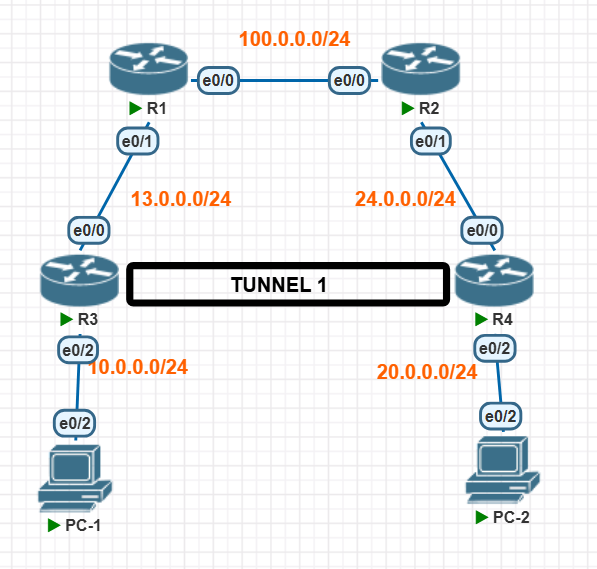
The network consists of two branch sites connected over an ISP backbone.
- ISP Core: R1 and R2 simulate the public internet core, routing traffic between the
13.0.0.0/24and24.0.0.0/24networks. - Branch Edge Routers: R3 and R4 act as the gateway routers for their respective LANs.
- GRE Tunnel: Tunnel 1 uses the
55.55.55.0/24subnet to encapsulate private LAN traffic over the public links.
| Device | Interface | IP Address | Subnet Mask |
|---|---|---|---|
| R1 (ISP) | e0/0 e0/1 |
100.0.0.1 13.0.0.1 |
255.255.255.0 255.255.255.0 |
| R2 (ISP) | e0/0 e0/1 |
100.0.0.2 24.0.0.2 |
255.255.255.0 255.255.255.0 |
| R3 (Branch 1) | e0/0 (WAN) e0/2 (LAN) Tunnel1 |
13.0.0.3 10.0.0.3 55.55.55.5 |
255.255.255.0 255.255.255.0 255.255.255.0 |
| R4 (Branch 2) | e0/0 (WAN) e0/2 (LAN) Tunnel1 |
24.0.0.4 20.0.0.4 55.55.55.10 |
255.255.255.0 255.255.255.0 255.255.255.0 |
Device Configurations
Apply the following configurations to establish underlying reachability and configure the GRE tunnel.
ISP Core Routers
R1 Configuration
R1>enable
R1#configure terminal
R1(config)#interface Ethernet0/0
R1(config-if)#ip address 100.0.0.1 255.255.255.0
R1(config-if)#no shutdown
R1(config-if)#exit
R1(config)#interface Ethernet0/1
R1(config-if)#ip address 13.0.0.1 255.255.255.0
R1(config-if)#no shutdown
R1(config-if)#exit
! Static route to reach R4's WAN segment
R1(config)#ip route 24.0.0.0 255.255.255.0 100.0.0.2
R2 Configuration
R2>enable
R2#configure terminal
R2(config)#interface Ethernet0/0
R2(config-if)#ip address 100.0.0.2 255.255.255.0
R2(config-if)#no shutdown
R2(config-if)#exit
R2(config)#interface Ethernet0/1
R2(config-if)#ip address 24.0.0.2 255.255.255.0
R2(config-if)#no shutdown
R2(config-if)#exit
! Static route to reach R3's WAN segment
R2(config)#ip route 13.0.0.0 255.255.255.0 100.0.0.1
Branch Edge Routers (GRE Tunnel Endpoints)
R3 Configuration
R3>enable
R3#configure terminal
! GRE Tunnel Configuration
R3(config)#interface Tunnel1
R3(config-if)#ip address 55.55.55.5 255.255.255.0
R3(config-if)#tunnel source Ethernet0/0
R3(config-if)#tunnel destination 24.0.0.4
R3(config-if)#exit
R3(config)#interface Ethernet0/0
R3(config-if)#ip address 13.0.0.3 255.255.255.0
R3(config-if)#no shutdown
R3(config-if)#exit
R3(config)#interface Ethernet0/2
R3(config-if)#ip address 10.0.0.3 255.255.255.0
R3(config-if)#no shutdown
R3(config-if)#exit
! Routing Private traffic over Tunnel1
R3(config)#ip route 20.0.0.0 255.255.255.0 Tunnel1
! Routing Public traffic via ISP
R3(config)#ip route 24.0.0.0 255.255.255.0 100.0.0.1
R3(config)#ip route 100.0.0.0 255.255.255.0 13.0.0.1
R4 Configuration
R4>enable
R4#configure terminal
! GRE Tunnel Configuration
R4(config)#interface Tunnel1
R4(config-if)#ip address 55.55.55.10 255.255.255.0
R4(config-if)#tunnel source Ethernet0/0
R4(config-if)#tunnel destination 13.0.0.3
R4(config-if)#exit
R4(config)#interface Ethernet0/0
R4(config-if)#ip address 24.0.0.4 255.255.255.0
R4(config-if)#no shutdown
R4(config-if)#exit
R4(config)#interface Ethernet0/2
R4(config-if)#ip address 20.0.0.4 255.255.255.0
R4(config-if)#no shutdown
R4(config-if)#exit
! Routing Private traffic over Tunnel1
R4(config)#ip route 10.0.0.0 255.255.255.0 Tunnel1
! Routing Public traffic via ISP
R4(config)#ip route 13.0.0.0 255.255.255.0 100.0.0.2
R4(config)#ip route 100.0.0.0 255.255.255.0 24.0.0.2
End Devices (PCs)
PC-1 Configuration
PC-1>enable
PC-1#configure terminal
PC-1(config)#interface Ethernet0/2
PC-1(config-if)#ip address 10.0.0.10 255.255.255.0
PC-1(config-if)#no shutdown
PC-1(config-if)#exit
PC-1(config)#ip route 0.0.0.0 0.0.0.0 10.0.0.3
PC-2 Configuration
PC-2>enable
PC-2#configure terminal
PC-2(config)#interface Ethernet0/2
PC-2(config-if)#ip address 20.0.0.10 255.255.255.0
PC-2(config-if)#no shutdown
PC-2(config-if)#exit
PC-2(config)#ip route 0.0.0.0 0.0.0.0 20.0.0.4
Verification
Once configured, verify the tunnel status and end-to-end connectivity:
- On R3 and R4, run
show interface tunnel 1and verify the status is up/up. - On PC-1, run
ping 20.0.0.10to verify private traffic is successfully routing through the encapsulated GRE tunnel.